Snow instructions
Snow build and light up instruction.


Build your Snow board
Yes "Snow board"
Prepare for the build
Before assembling the tree, please make sure you are good to go!
- Soldering iron
- Solder wire - with rosin or use Flux
- Micro USB cable to connect with your computer
- Tweezer - to grab small parts. It's really tiny.
parts list
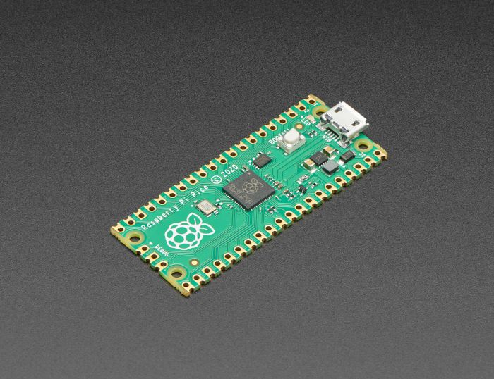
- Raspberry Pi Pico x 1
- chip LEDs
- 1000 ohm resistor x 9
If you are new to soldering, watch this video first, This video explain what should be done for SMD parts.

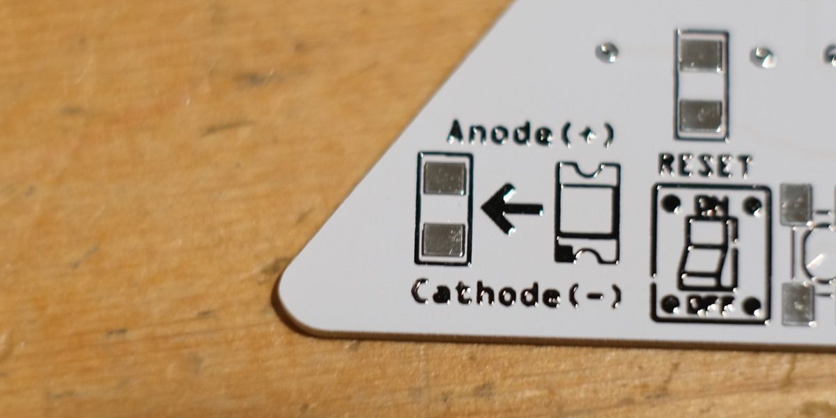
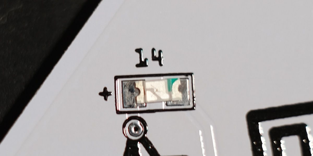
Polarity of the LED
Before soldering chip LEDs, it is important to know the polarity of the LED, as reversing the polarity will prevent the LED from lighting up.
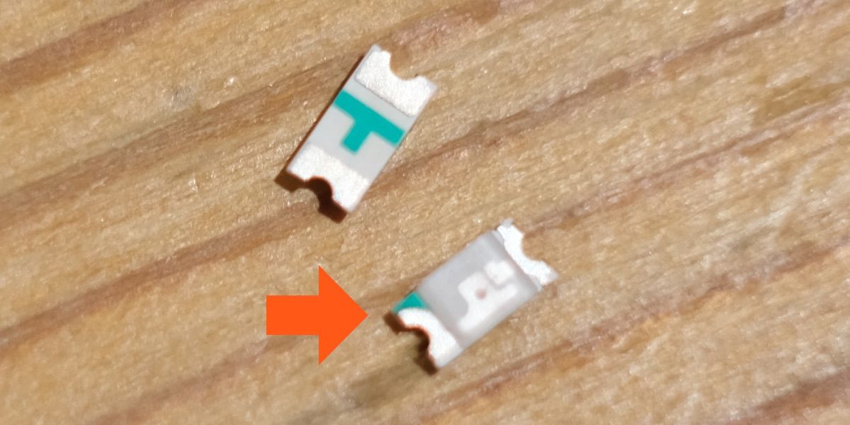
The polarity of SMD (surface-mount device) LEDs is determined by the green mark.

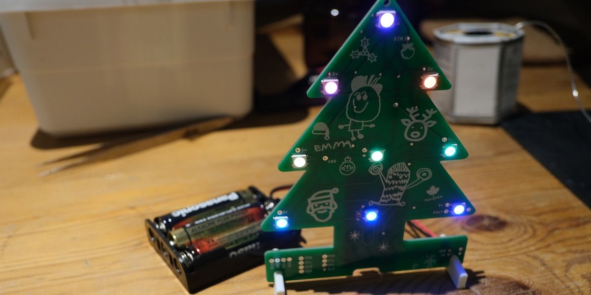
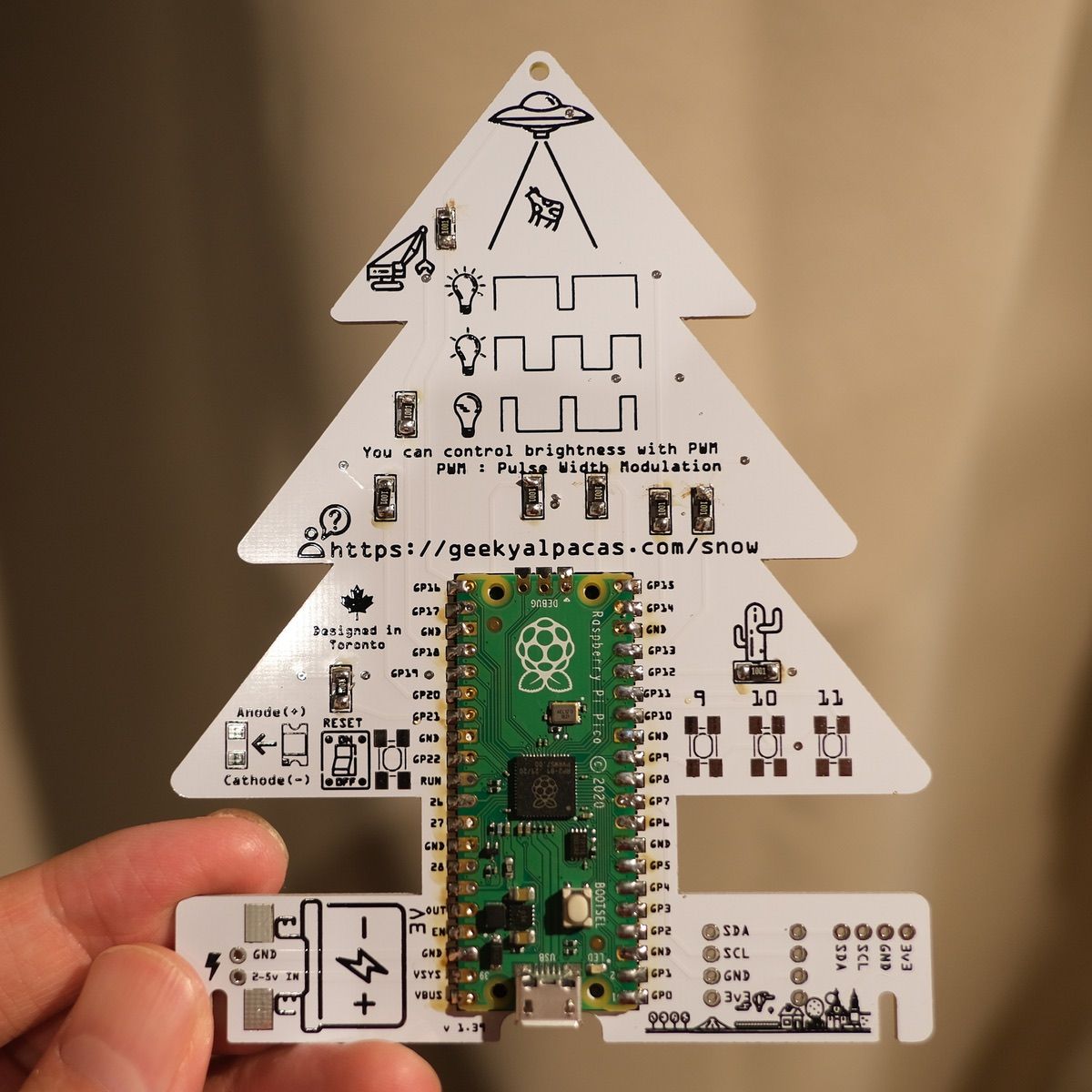
Let's solder all LEDs
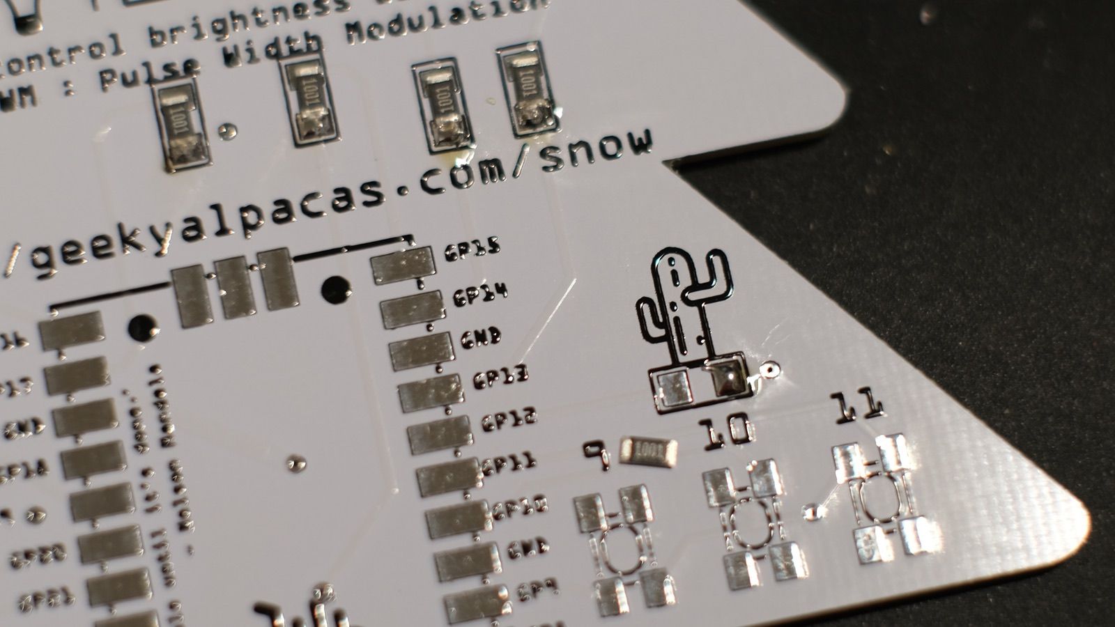
Check direction and solder all leds. Once you finish the LEDs, your PCB will be like below.

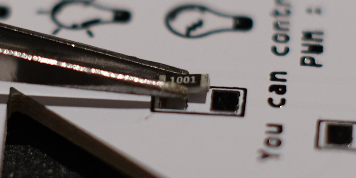
Flip the PCB and go for resistors.
There is No polarity of resistor, so you can solder it as you want ;)
100% power of LED is too bright?
Yes, it is possible that setting the LED to 100% power could make it too bright. The brightness of an LED is determined by the amount of current that is supplied to the LED, and increasing the current can make the LED brighter. However, if the LED is supplied with too much current, it could be damaged or even destroyed.
Therefore, it is generally recommended to use a current-limiting resistor in series with the LED to limit the amount of current flowing through the LED. This will prevent the LED from being damaged by excessive current, and it will also allow you to adjust the brightness of the LED by controlling the amount of current flowing through it.

Once you finish the resistors, then go for Raspberry Pi Pico.
Let's get it work
Connect USB cable to Raspberry Pi Pico
Connect your computer to Raspberry Pi Pico.
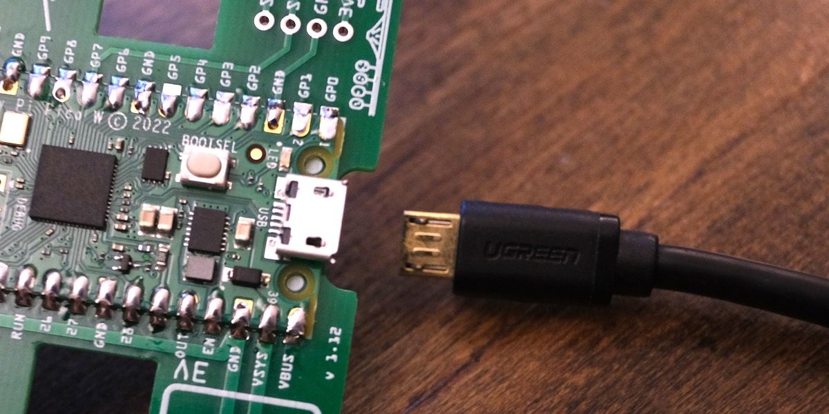
When it connected, you will see the icon on the Desktop (if you are using macOS/Windows/Raspberry Pi OS).

What is CircuitPython?
CircuitPython is an open-source programming language based on Python. It is specifically designed to be used with microcontroller boards, such as Raspberry Pi Pico.
CircuitPython is a variant of MicroPython, which is a compact version of Python that can run on microcontrollers with limited memory and processing power. CircuitPython adds support for specific microcontroller boards and adds a number of features and libraries for interacting with hardware devices, such as sensors, motors, and displays.
Setup CircuitPython for Raspberry Pi Pico
Download CircuitPython firmware. As of today (November 20, 200), the latest stable version is 7.3.3
Download it from here

Click on the "DOWNLOAD .UF2 NOW" button.
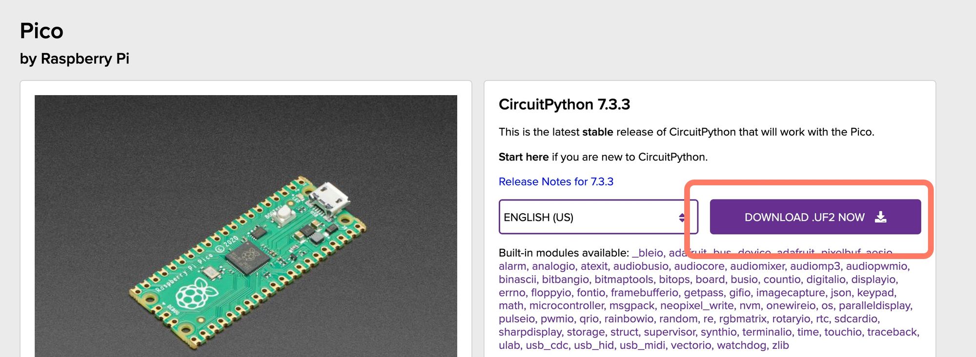
Once you downloaded, drag and drop the file to RPI-RP2. It may take 20~30 seconds.

🍎Are you using macOS 13 Ventura?
macOS 13 Venture is not support well with Raspberry Pi Pico. When you connect Raspberry Pi Pico to your computer, mass storage device will show up, however, you cannot directly drag and drop the UF2 file (It will be failed with error code 100093)
But there is a good news, you can copy the file with terminal, so open up the terminal and copy the UF2 file to Raspberry Pi Pico. (Usually pico is mounted as /Volumes/RPI-RP2/)
e.g. copy command
cp adafruit-circuitpython-raspberry_pi_pico-en_US-7.3.3.uf2 /Volumes/RPI-RP2/
If you don't know what to do, ask me at @kotaMorishita
Set up the tree
Download Development Tool

Download and install Thonny to your computer.
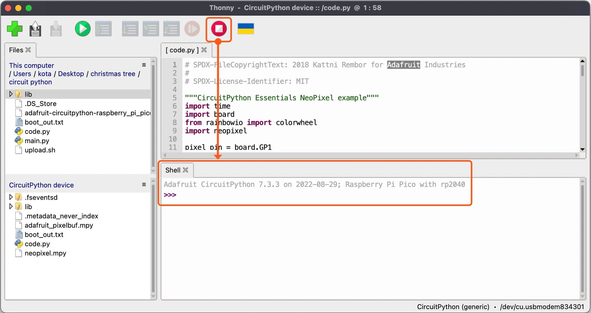
Press the red button.
When you press the red button (with white square at the center), "Shell" will be refreshed. also If something is not working, hit the red button anytime!
After you hit the button, CircuitPython version will show up in "Shell" tab.
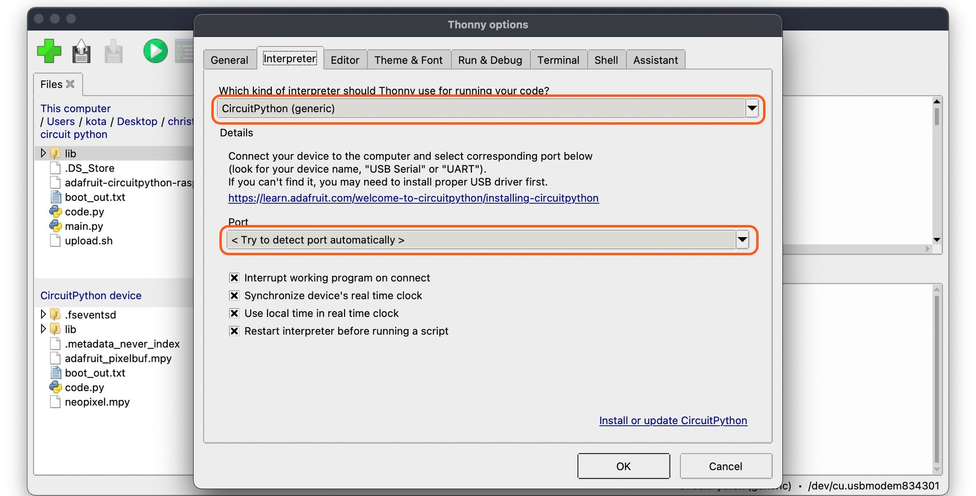
If nothing happens, Go to Thonny -> Preferences -> "Interpreter" tab to ensure CircuitPython is selected, also Port is <Try to detect port automatically>
Then press "ok" to close the preference menu.
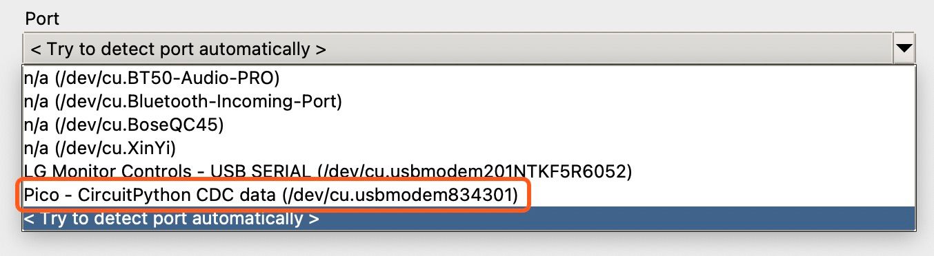
Still not working?
Automatic setting should work most of cases, but if it doesn't work with your setup, select the Pico - CircuitPython
Sample program
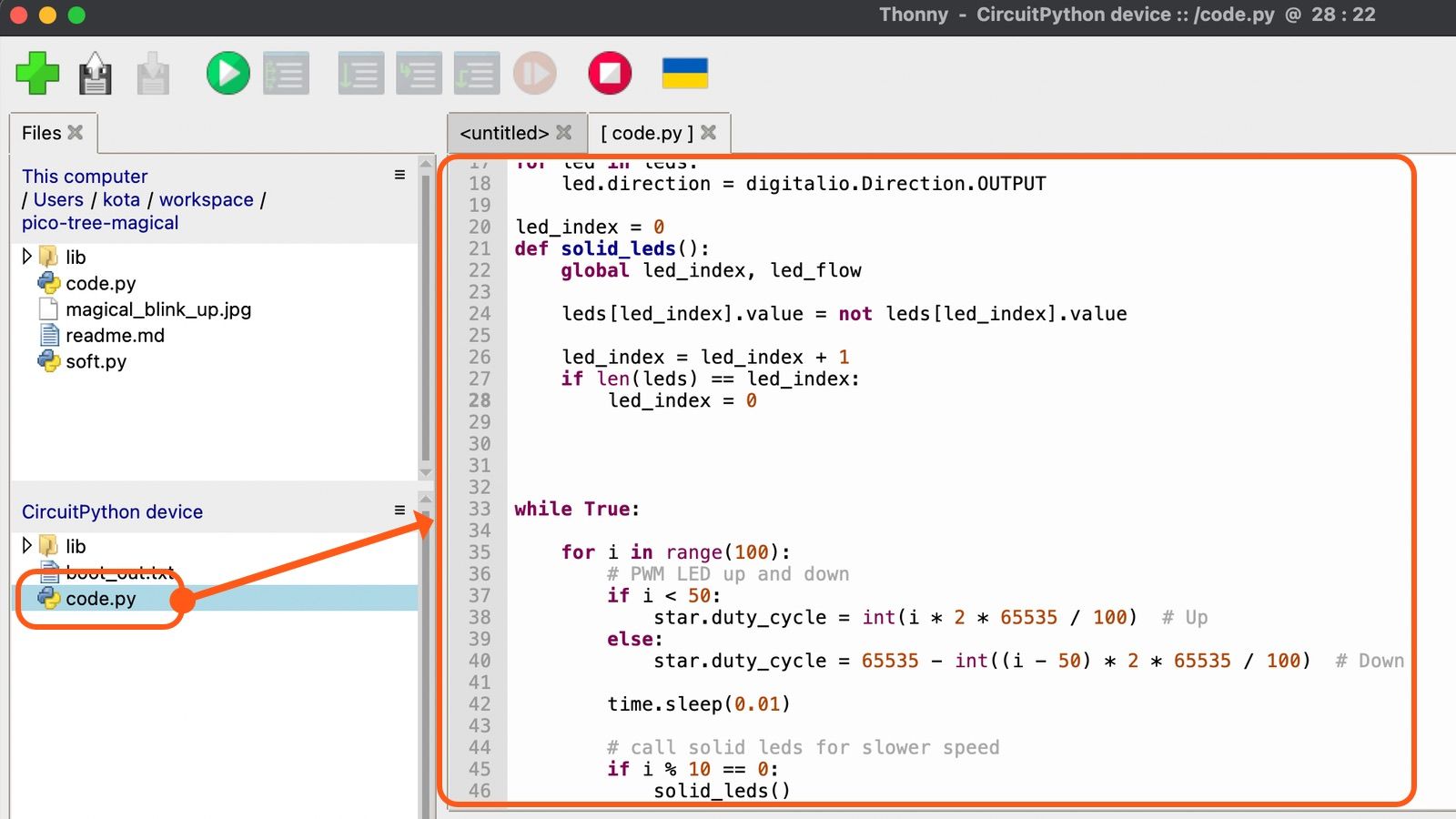
Double click on the code.py to open the program, then copy and paste this code.
To run the progam, hit the green button!
import time
import board
import pwmio
import digitalio
import random

star = pwmio.PWMOut(board.GP16, frequency=5000, duty_cycle=0)
leds = [digitalio.DigitalInOut(board.GP14),
                digitalio.DigitalInOut(board.GP19),
                digitalio.DigitalInOut(board.GP13),
                digitalio.DigitalInOut(board.GP17),
                digitalio.DigitalInOut(board.GP20),
                digitalio.DigitalInOut(board.GP12),
                digitalio.DigitalInOut(board.GP15),
                digitalio.DigitalInOut(board.GP21)]

for led in leds:
    led.direction = digitalio.Direction.OUTPUT

led_index = 0
def solid_leds():
    global led_index, led_flow

    leds[led_index].value = not leds[led_index].value

    led_index = led_index + 1
    if len(leds) == led_index:
        led_index = 0


while True:

    for i in range(100):
        # PWM LED up and down
        if i < 50:
            star.duty_cycle = int(i * 2 * 65535 / 100)  # Up
        else:
            star.duty_cycle = 65535 - int((i - 50) * 2 * 65535 / 100)  # Down

        time.sleep(0.01)

        # call solid leds for slower speed
        if i % 10 == 0:
            solid_leds()
This code use one PWM to slowly blink top-of-tree LED. Other LEDs are turned on and off in turn to follow.
Not working?
If entire LEDs are not blinking, it may software problem. Disconnect and reconnect USB cable and then run the code.
If one/few LEDs are not blinking, it might be hardware problem. It most likely wrong direction of LED or not soldered well. please check LED/resistor pair is solered properly.
What is PWM?
Pulse width modulation (PWM) is a type of digital signal that is used to control the brightness of a light or the speed of a motor. PWM signals are a series of digital pulses that are used to control the amount of power that is delivered to a device. The width of the pulse determines the amount of power that is delivered, with wider pulses resulting in more power and narrower pulses resulting in less power. PWM signals are often used in applications where it is necessary to control the intensity of a light. This sample program is handling LED brightness at the top of tree!
star = pwmio.PWMOut(board.GP16, frequency=5000, duty_cycle=0)while True:
for i in range(100):
# PWM LED up and down
if i < 50:
star.duty_cycle = int(i * 2 * 65535 / 100) # Up
else:
star.duty_cycle = 65535 - int((i - 50) * 2 * 65535 / 100) # Down
time.sleep(0.01)Stop the program
When program is running on your Raspberry Pi Pico, they are not able to read/write files. Press the Red button first, then open or replace files.
Super Simple Sample
"SSS"
Here is the example of super simpe code. this code makes just one LED on and off every second.
import time
import board
import digitalio

led = digitalio.DigitalInOut(board.GP17)
led.direction = digitalio.Direction.OUTPUT

while True:
    time.sleep(1)
    led.value = 1
    time.sleep(1)
    led.value = 0
import
In Python(and CircuitPython), the import keyword is used to import external modules into the current Python program. This allows you to use the functions, classes, and other features of the imported module in your program. For example, you can use the import keyword to import the time module, which contains many time related functions, and then use those functions in your program. Here is an example:
import time

# wait for 3 seconds
time.sleep(3)
digitalio
The digitalio module for control GPIO. This tree PCB is directly connected GPIO to LED, so when we ON the GPIO, LED will be turned on.
led = digitalio.DigitalInOut(board.GP15)
led.direction = digitalio.Direction.OUTPUT
And here is the API manual. In this article, we use CircuitPython vesion 7.3.3
Loop it forever
while True:
    time.sleep(1)
    led.value = 1
    time.sleep(1)
    led.value = 0
while True:: This line of code creates an infinite loop that will repeat the code inside the loop indefinitely.time.sleep(1): This line of code uses thesleep()function from thetimemodule to wait for 1 second.led.value = 1: This line of code sets thevalueproperty of theledobject to 1. This will turn on the LED.time.sleep(1): wait 1 second again, otherwise led on duration is too short to see by human eyes!!led.value = 0: This line of code sets thevalueproperty of theledobject to 0. This will turn off the LED.
CircuitPython vs Python
In contrast, regular Python is a general-purpose programming language that is not specifically designed for use with microcontrollers. It can be used for a wide range of applications, from web development and data analysis to scientific computing and machine learning.
The main differences between CircuitPython and regular Python are as follows:
- CircuitPython is specifically designed for use with microcontroller boards, while regular Python is a general-purpose programming language.
- CircuitPython adds support for specific microcontroller boards and includes a number of libraries for interacting with hardware devices, such as sensors, motors, and displays. Regular Python does not include these features by default.
- CircuitPython is intended to be simple and easy to learn, making it well-suited for beginners and hobbyists. Regular Python can be more complex, with a wider range of features and a steeper learning curve.
Overall, CircuitPython is a good choice if you want to quickly prototype interactive electronic projects using microcontroller boards, while regular Python is a better choice for more general-purpose programming tasks.
However regular Python is bit too heavy to run on Raspberry Pi Pico.
Need help?
If you need some help for Snow PCB, please contact me @kotaMorishita

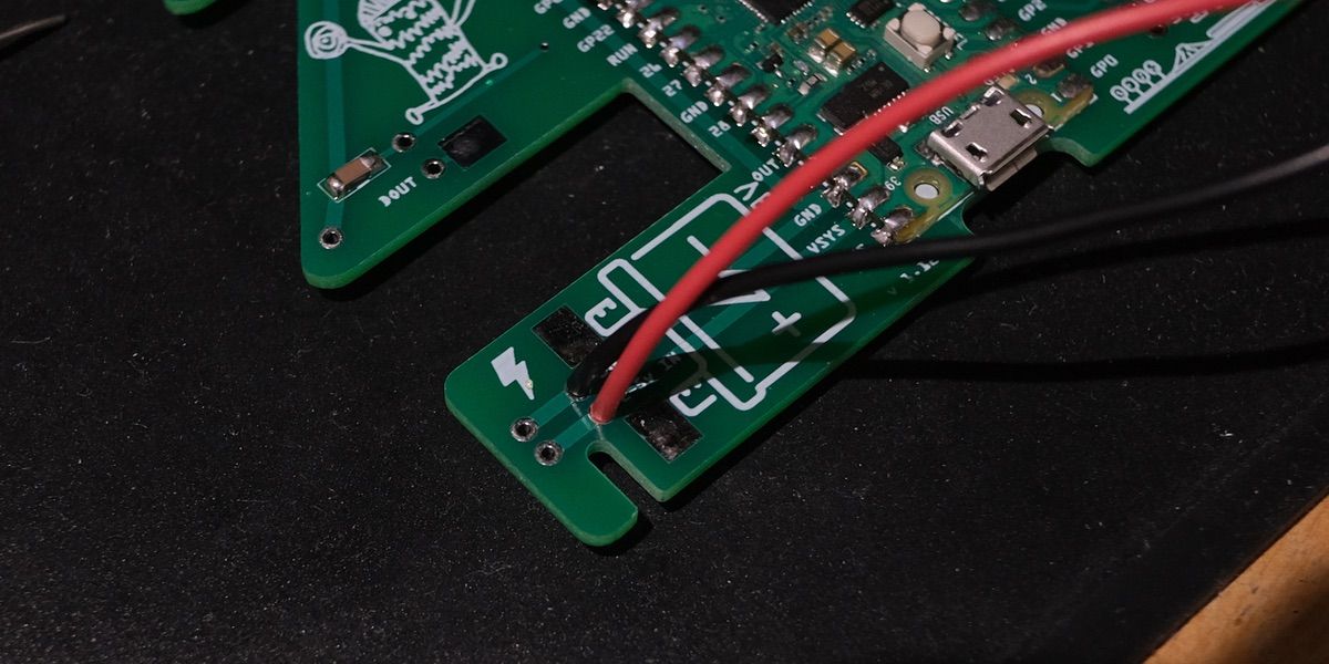
Optional : Battery Powered Tree
You can light up the tree with battery power.
⚠ DO NOT connect USB and battery at the same time. It may break your computer or tree!!
Connect red wire to +(Positive) side, black to the -(Negative) side.